Home Automation with Raspberry Pi and Relay Module
Sun 22 Nov 2015, 17:11
While I was looking for my raspberry accessories, suddenly I found 8 channel relay module for only Rp. 53.000, it is very cheap and I decide to buy it and start playing with this module.
With this relay module i can control any kind of high voltage switch (220v) in my house from my mobile phone, but we have to very careful if we are playing with high voltage, it can cause very bad injury or even death.
For the first thing I want to do is to control the bedroom lamp and the night lamp, so when I go to sleep, I don’t need to get up from bed to turn off the bedroom lamp and turn on the night lamp, just touching my mobile phone or even I can make a schedule for this.
Prepare your Raspberry Pi
Check gpio command on your raspberry os, type this command in terminal:
gpio
if command not found, you need to install wiringPi library created by Gordon Henderson so that you can use simple command line to access raspberry gpio.
http://wiringpi.com/download-and-install/
https://projects.drogon.net/raspberry-pi/wiringpi/the-gpio-utility/
If you want to know more about GPIO, you can read this:
http://luketopia.net/2013/07/28/raspberry-pi-gpio-via-the-shell/
http://elinux.org/RPi_Low-level_peripherals
https://www.raspberrypi.org/documentation/usage/gpio/
Prepare your Hardware
This is what you need:
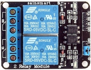
2 channel relay module
Above relay module for 2 switches.
- Female to Female Jumper Wires
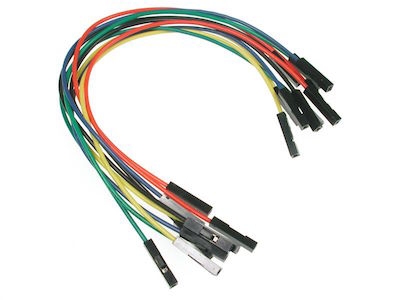
Jumper wires
We need this to connect raspberry gpio pin and relay module pin, for 2 channel relay module you need 4 jumper wires, for 8 channel relay module you need 10 jumper wires (2+n channel)
Connection between raspberry gpio pin and relay module
- Physical Pin
This is raspberry physical pin number from 1 to 40.
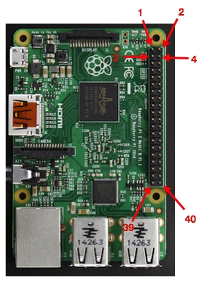
Raspberry Pi 2 B
- GPIO Detail Information
If you already install wiringPi, type this command in terminal:
gpio readall
It will show you detail information about what each pin for, pin mode, pin status, or map between physical pin and wiring pi that you will use in the command later.

GPIO Detail Information
For this relay, I use pin number with name contain GPIO.
- Raspberry Pi and Relay Module Wiring.
If you already know which physical pin number you will use, start to connect your raspberry pi and relay module use jumper wires.

Wiring Schematic
In above wiring schema, I use:
- Pin 2 (5v) connect to Relay Module VCC Pin because this module needs 5volt power.
- Pin 6 (0v) connect to Relay Module GND Pin.
- Pin 12 (GPIO. 1) connect to Relay Module IN1 for Switch 1.
- Pin 16 (GPIO. 4) connect to Relay Module IN2 for Switch 2.
- Relay Port
Relay module has 3 ports for each switch
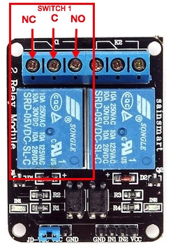
Relay port
This is the explanation about that ports:
- C (Common Connection)
High Voltage Power connected to this port.
- NC (Normally Close Connection)
When the relay not active or default state, this port will always connected to C port. When active and we trigger the relay it will not connected to C depend on what state we give to the relay.
- NO (Normally Open Connection)
This port is opposite of the NC Port. When the relay not active or default state, this will not connected to C port. When active and we trigger the relay it will connected to C depend on what state we give to the relay.
- Test the connection
Before you connect your relay module to the lamp, will better if you test it first.
First, find what is wPi number for each gpio pin we use, wPi number will be use in the command later. This is the wPi Number for pin 12 and pin 16:
- Pin 12 to wPi 1
- Pin 16 to wPi 4
After you discover the wPi Number and then use below command to changing the gpio mode “in” or “out”. For this relay module we will use “out” mode.
gpio mode <wpi> out
After changing the gpio mode, we will change the value to 1 (HIGH) or 0 (LOW). Because this relay is HIGH state Type, so when we give HIGH state to the relay it will turn off and it will turn on when in LOW State.
gpio write <wpi> <value>
And this is the command:
gpio mode 1 out
gpio mode 4 out
There is LED Light for each switch in the relay board. LED Light will On when connected to NO Port and LED Light will Off when the opposite.
Type this command for LOW State/Turn On/LED Light On/Connected to NO:
gpio write 1 0
gpio write 4 0
Type this command for HIGH State/Turn Off/LED Light Off/Connected to NC:
gpio write 1 1
gpio write 4 1
- Relay module electrical installation.
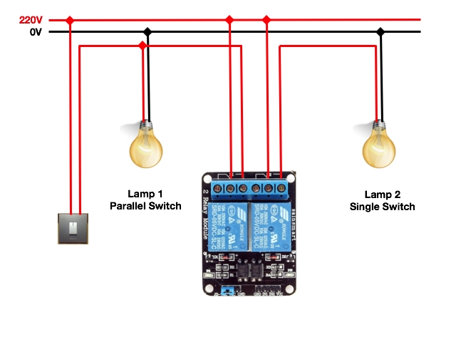
After you do the test, now you can do the electrical installation. This is the electrical diagram wiring:

Electrical Diagram Wiring
It will be better if you use parallel switch schema, so when suddenly your relay module not working, you still can use your manual switch to turn On your lamp.
Implementation of My Relay Module
I have 2 kinds of relay module:
- 2 channel relay module use for controlling bedroom lamp and night lamp.
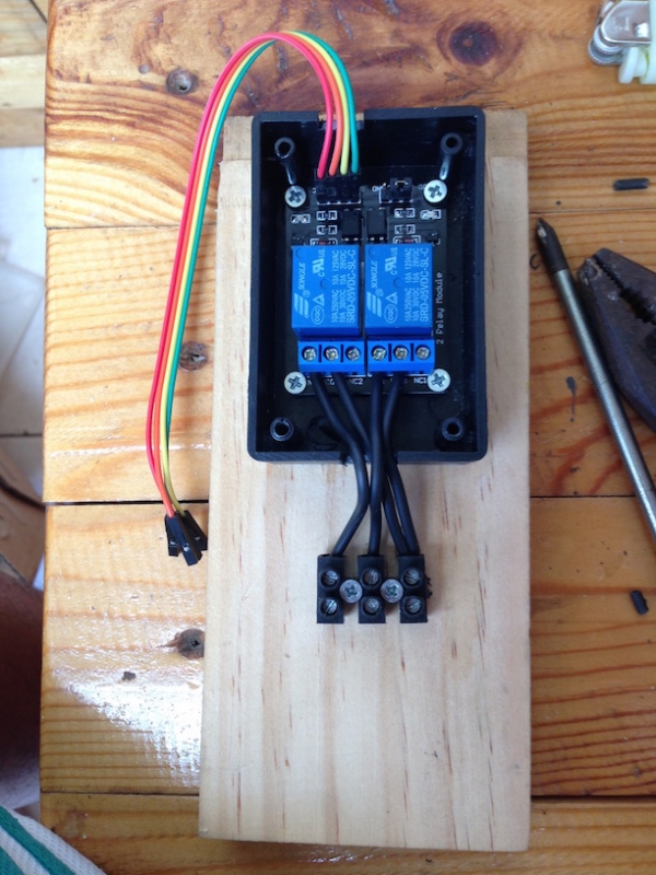
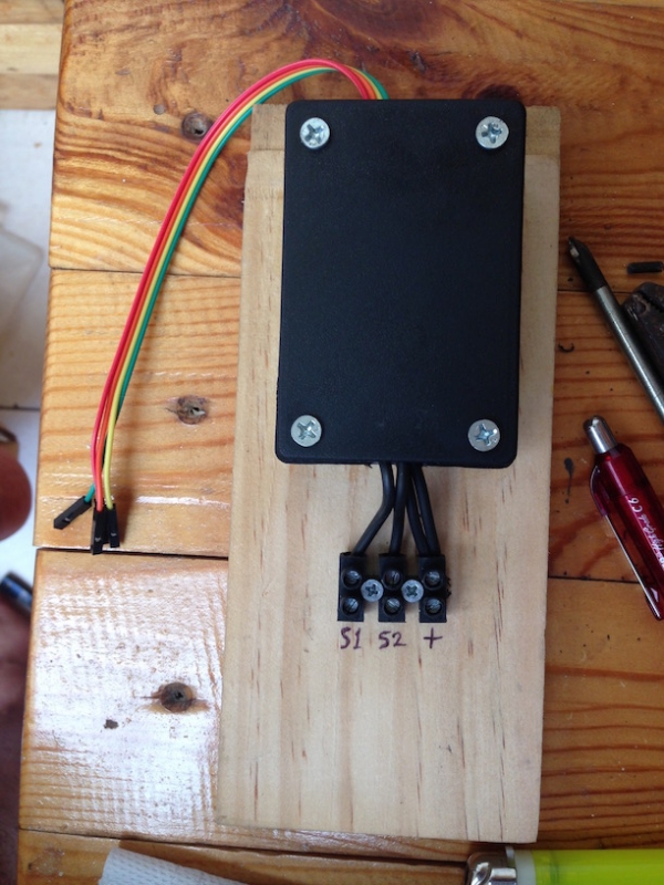
2 channel relay
- 8 channel relay module use for controlling 6 outlet power strips, I use this for sound system power in my room.
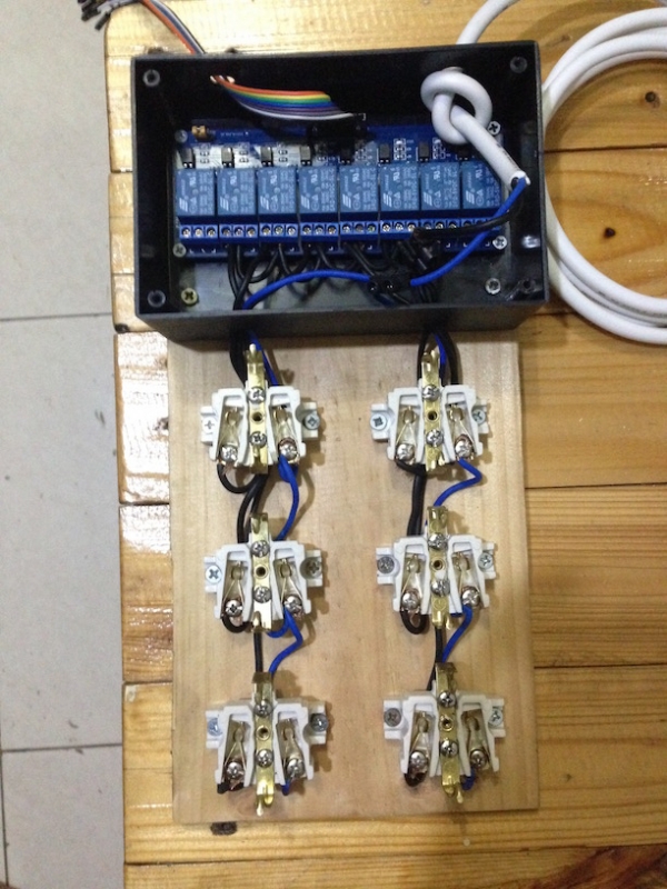
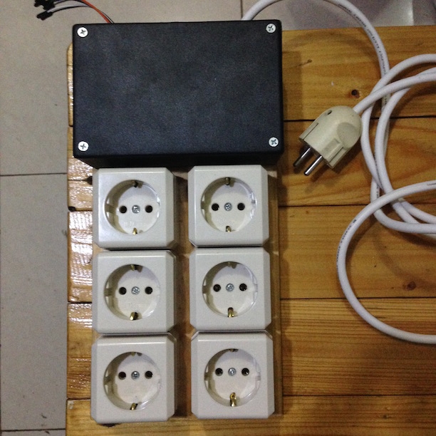
8 channel relay module for 6 outlet power strips
Controller Application
To control my relay module, I made a simple application. If you have home server like what I wrote earlier Mini HOME SERVER Using Raspberry Pi 2 B , you can control your home anywhere. This is my application:
- Web Application
I am using PHP for this and just simply use shell_exec function to execute the command line, css for the switch, and responsive web design so that I just need to make single application for desktop and mobile. You can download my source code at Download
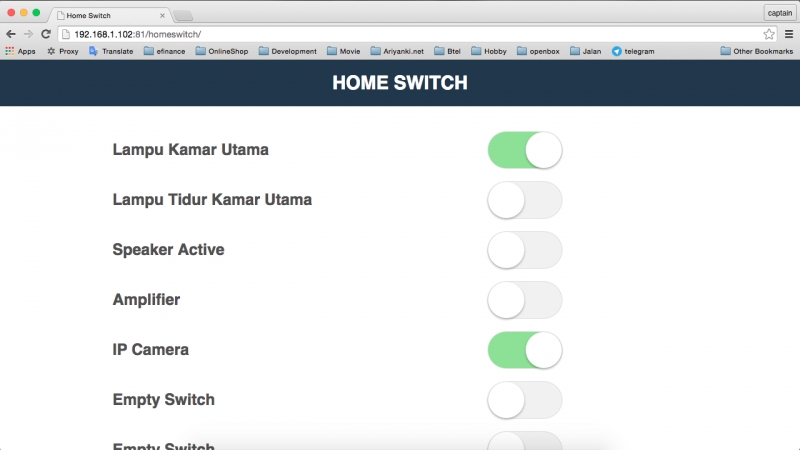
Desktop Web Base Switch Controller
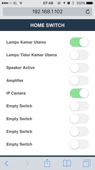
Mobile Web Base Switch Controller
- Mobile Application.
If you want to make a mobile application so that you don’t hove to open browser and type the url of your web application, you just simply need to make mobile app use Web View Client and point the url to your web application.
This is my IOS Mobile App, I name it Home Switch App:

Home Switch App Icon
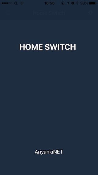
Home Switch Launch Screen
This is the main screen:

Home Switch Web View Client use UIWebView
You have to make configuration screen so that if you change your web application url, you just need to change the url from this screen.
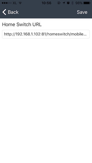
Home Switch Url Configuration
That’s it, very nice to share, I hope this will help us and make our life easier.
By Ariyanki
4
16200 views
